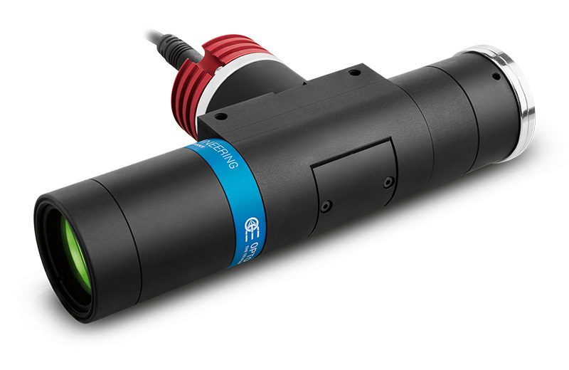
TCCX series
132mm working distance coaxial telecentric lenses for sensors up to 2/3”

Key advantages
- Large numerical aperture
For small pixel size/high-resolution sensors. - Long working distance
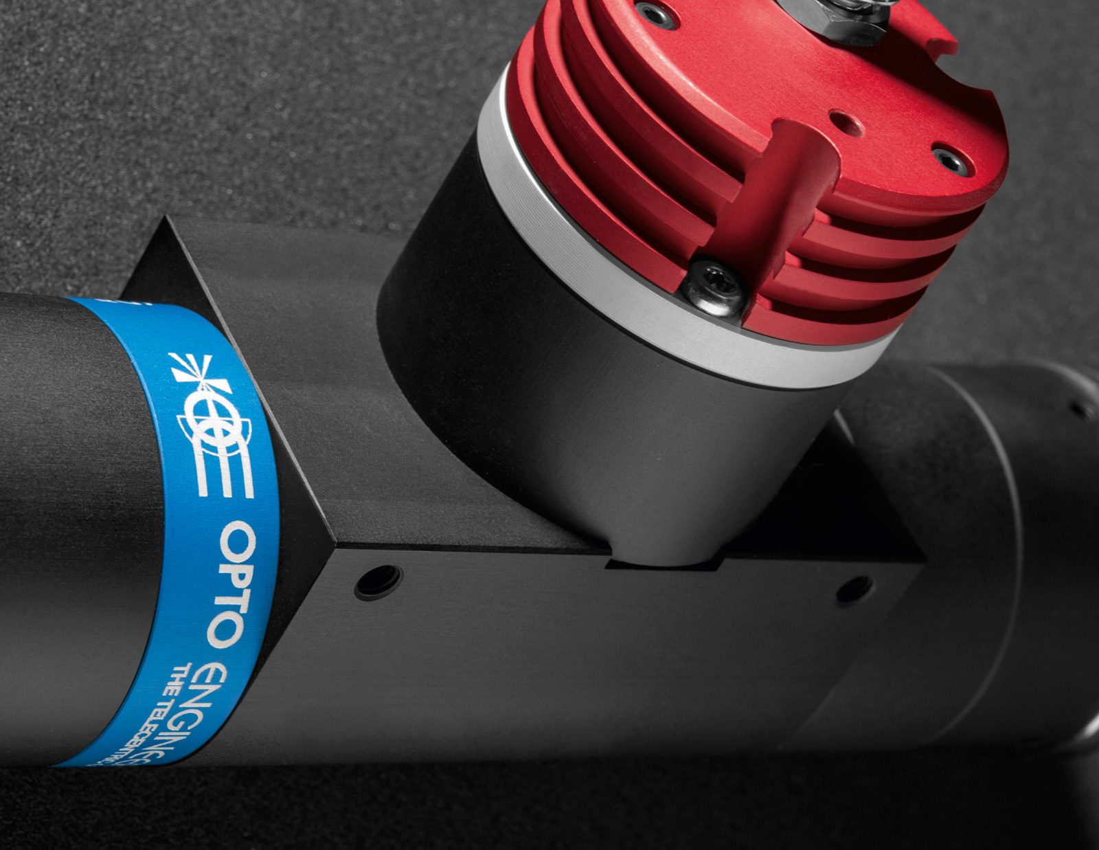
Tailored for electronic components inspection. - Compact built-in illumination
Ideal for high-end applications in semiconductor industry. - Easy rotational phase adjustment
Robust and precise tuning of the camera phase. - Detailed test report with measured optical parameters.
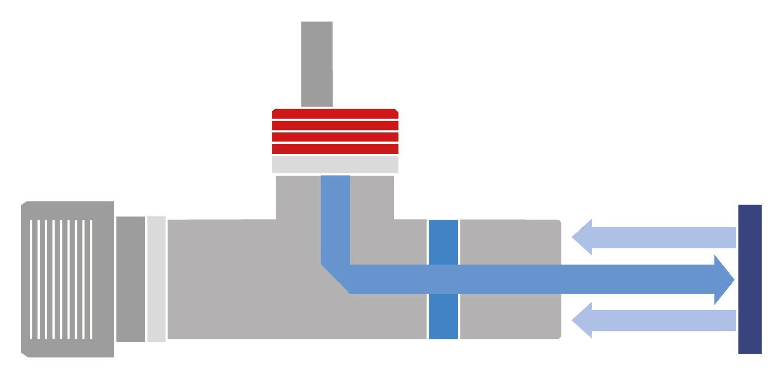
TCCX series is a range of lenses designed for measurement and defect detection on flat surfaces. They feature the same magnifications and working distance of TCLWD series while adding integrated coaxial light.
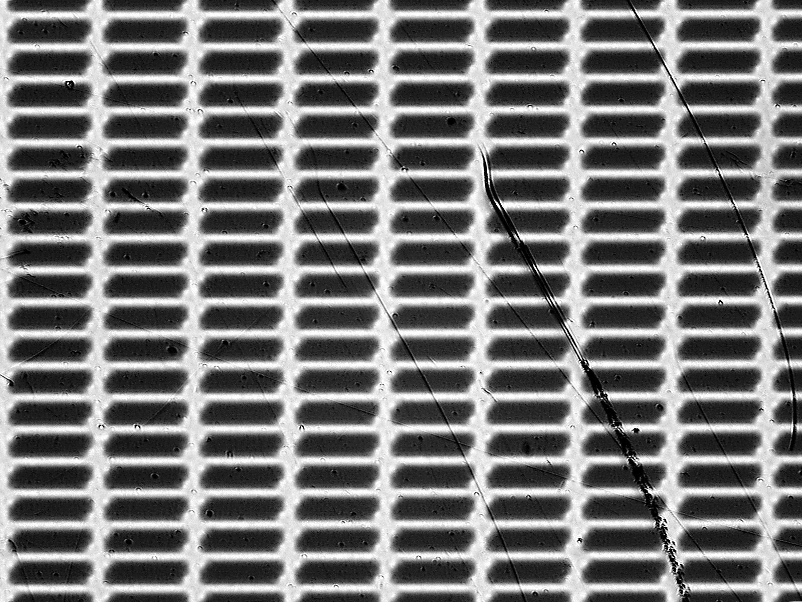
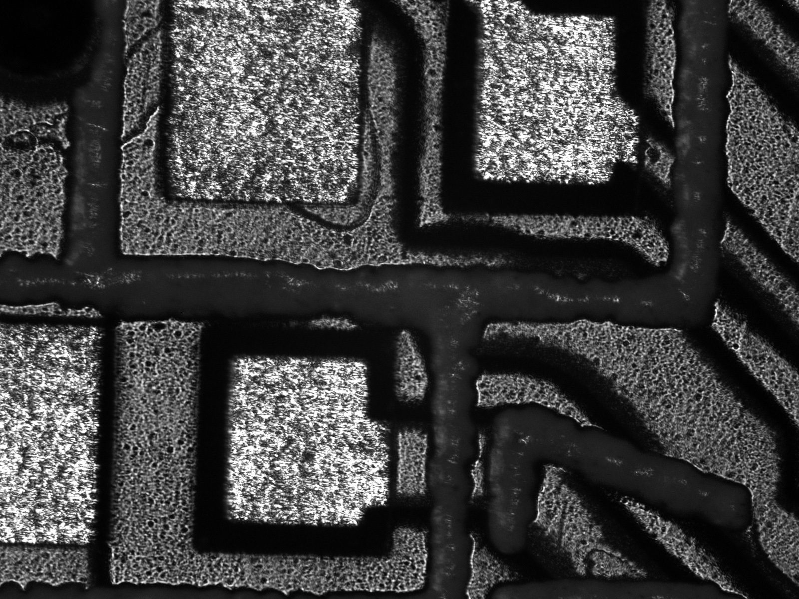
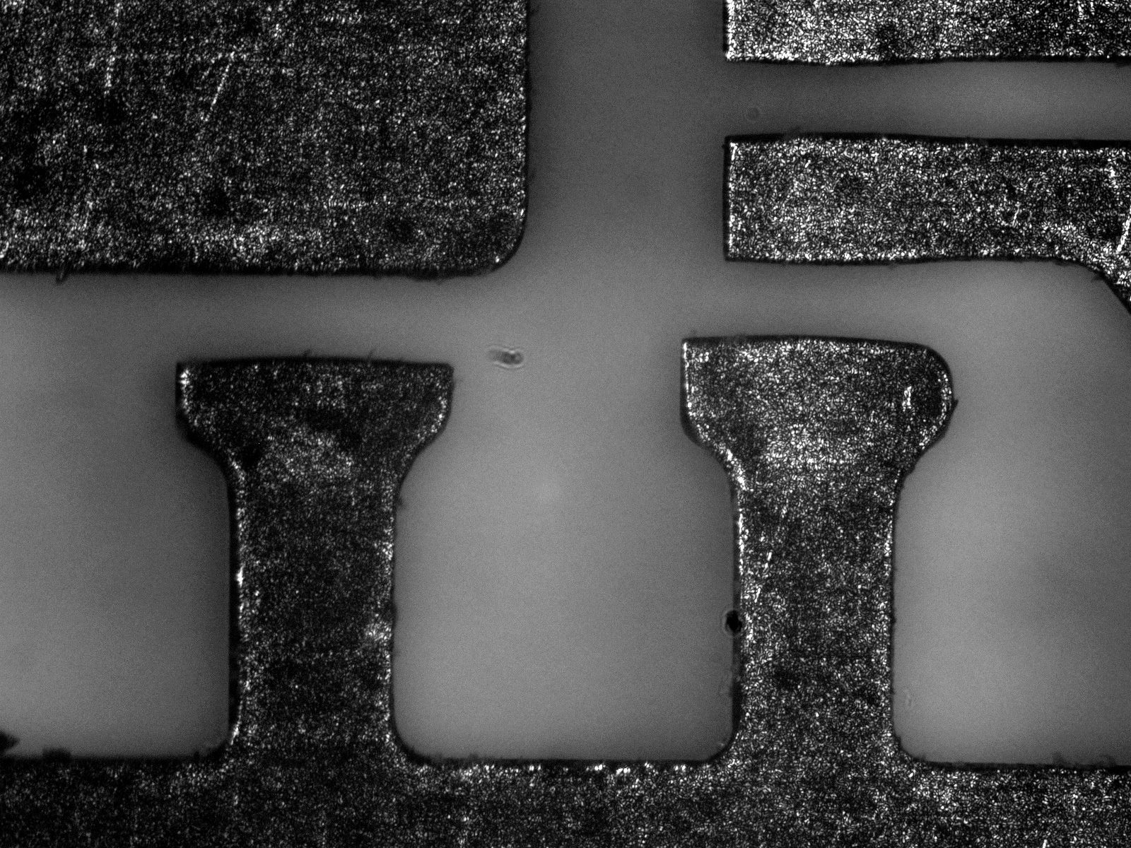
Such lighting configuration is required to homogeneously illuminate uneven surfaces and detect small surface defects such as scratches or grooves, finding application in many industries, from the electronics and semiconductor industries to the glass and metal fabrication industries.
All these lenses operate at a working distance of 132 mm while their large numerical aperture enables the superior resolution needed for small pixel cameras, matching and even exceeding the industrial requirements of on- and offline applications.
The built-in LED source, equipped with advanced electronics, provides excellent illumination stability and homogeneity, key factors for the reliability of any machine vision system.
The unique optical design minimizes the internal reflection issues of conventional coaxial illumination systems: this makes TCCX lenses the perfect choice especially when inspecting highly reflective flat surfaces (approx. > 30% reflectance).
Typical application include recognition of silicon wafers pattern and inspection of LCD displays, polished metal surfaces, plastic and glass panels, and many other.
Note: for opaque samples (reflectance <30%) please refer to TCCXQ Series
New
It is possible to integrate liquid lens technology on all models of the TCCX series to allow fast and precise refocusing. Contact our sales engineers to discuss your specific needs.
Real-world application examples and case histories
Notes
- Working distance: distance between the front end of the mechanics and the object. Set this distance within ± 3% of the nominal value for maximum resolution and minimum distortion.
- Working f-number (wf/N): the real f-number of a lens in operating conditions.
- Maximum angle between chief rays and optical axis on the object side. Typical (average production) values and maximum (guaranteed) values are listed.
- Percent deviation of the real image compared to an ideal, undistorted image. Typical (average production) values and maximum (guaranteed) values are listed.
- At the borders of the field depth the image can be still used for measurement but, to get a very sharp image, only half of the nominal field depth should be considered. Pixel size used for calculation is 3.45 μm.
- Object side, calculated with the Rayleigh criterion with λ= 520 nm
- At max forward current. Tolerance is ± 0.06V on forward voltage measurements.
- Used in continuous (not pulsed) mode.
- At pulse width <= 10 ms, duty cycle <= 10% condition. Built-in electronics board must be bypassed (see tech info).
- Measured from the front end of the mechanics to the camera flange.
Ordering information
Instructions for use
Operation options
LTSCHP LED modules can be operated in two ways:
- standard usage option: through the built-in electronics
- direct LED control usage option
STANDARD usage option (LED control through built-in electronics)
Only continuous mode (constant voltage) is allowed.
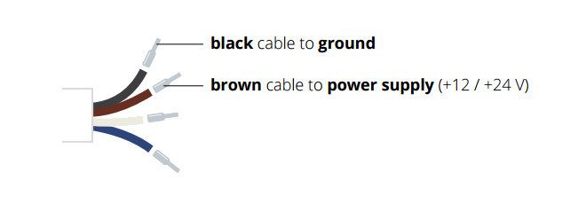
Connection:
Connect the black and brown cables to your +12 / +24 V power supply.
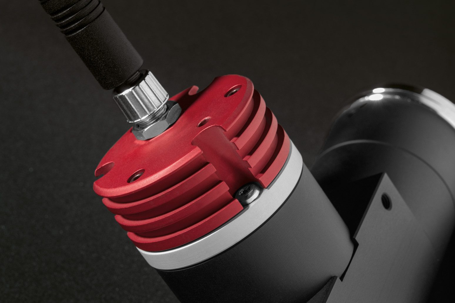
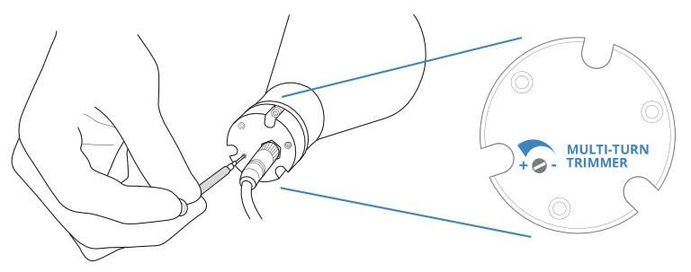
Light intensity adjustment
The built-in multi-turn trimmer allows to control the light (LED forward current) intensity with a very high degree of precision: you can bring the current intensity from minimum to maximum with 21 full turns of the adjustment screw. Simply remove the protective cap and rotate counter-clockwise the adjustment screw to increase light intensity and vice versa.
| Device power ratings | LED power ratings | |||||||||
|---|---|---|---|---|---|---|---|---|---|---|
| Part number | Light color, Wavelength peak |
DC voltage 1 | Power consumption |
Max LED forward current |
Forward voltage |
Max pulse current | Compatibility | |||
| Minimum | Maximum | Typical | Maximum | |||||||
| (V) | (V) | (W) | (mA) | (V) | (V) | (mA) | ||||
| 2 | 3 | 4 | 5 | 7 | ||||||
| LTSCHP1W-R Replacement LED module, red |
red, 630 nm | 12 | 24 | < 2.5 | 350 | 2.4 | 3.00 | 2000 | LTCLHP, TCBENCH, LTCL4K, TCCX, TCCXQ , LTCLHP CORE, TCBENCH CORE, TCKIT, MZMT12X |
|
| LTSCHP1W-G Replacement LED module, green |
green, 520 nm | 12 | 24 | < 2.5 | 350 | 3.3 | 4.00 | 2000 | LTCLHP, TCBENCH, LTCL4K, TCCX, TCCXQ , LTCLHP CORE, TCBENCH CORE, TCKIT, MZMT12X |
|
| LTSCHP1W-B Replacement LED module, blue |
blue, 460 nm | 12 | 24 | < 2.5 | 350 | 3.3 | 4.00 | 2000 | LTCLHP, TCBENCH, LTCL4K, TCCX, TCCXQ , LTCLHP CORE, TCBENCH CORE, TCKIT, MZMT12X |
|
| LTSCHP1W-W Replacement LED module, white |
white | 12 | 24 | < 2.5 | 350 | 2.78 | - | 2000 | LTCLHP, TCBENCH, LTCL4K, TCCX, TCCXQ , LTCLHP CORE, TCBENCH CORE, TCKIT, MZMT12X | |
- Tolerance ± 10%
- Used in continuous (not pulsed) mode.
- At max forward current.
- Tolerance is ±0.06V on forward voltage measurements.
- At pulse width <= 10 ms, duty cycle <= 10% condition. Built-in electronics board must be bypassed (see tech info).
- Shipped not assembled. See LTCLHP instruction manual.
- Some part numbers are not available in all color options (-R, -G, -B and -W). See page of each product series for available colors.
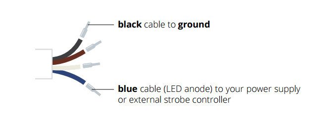
Direct LED control usage option
Both continuous and pulsed mode are allowed; the built-in electronics can be bypassed in order to drive the LED directly for use in continuous or pulsed mode. When bypassed, builtin electronics behaves as an open circuit allowing direct control of the LED source. Please note that in such case light intensity adjustment is not possible though the built-in multi-turn trimmer.
Connection:
Connect the black and blue cables as shown below (remove the LED anode protective cover).